Meets
(U.S. Federal Specification)
RR-C-271D Type XIV
FDIA
(MIN HOLE DIAMETER REQUIRED)
TO PASS EYE DURING ASSEMBLY
Chain Size
Weight Each (Lbs)
Working Load Limit (Lbs)
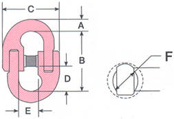
Dimensions (In.)
(In.)
(mm)
A
B
C
D
E
F
9/32 (1/4)
7
0.29
3500
0.36
1.88
1.75
0.80
0.64
0.63
5/16
8
0.67
4500
0.42
2.13
1.97
0.91
0.69
0.63
3/8
10
0.56
7100
0.48
2.50
2.50
1.06
0.88
0.84
1/2
13
1.06
12000
0.64
3.44
3.22
1.49
1.13
1.06
5/8
16
2.43
18100
0.75
4.13
3.78
1.79
1.41
1.25
3/4
20
4.20
28300
0.89
4.62
4.62
1.77
1.59
1.28
7/8
22
6.80
34200
1.05
5.97
5.59
2.45
1.86
1.44
Ultimate Load 4 times Working Load Limit
Individually Proof Tested at 2 times Working Load Limit with certification.
Locking system that provides for simple assembly and disassembly - no special tools needed.
Forged Alloy Steel - Quenched and Tempered.
Fatigue rated.
Quick System Chain Assemblies most ideal for any application, Fast & Ready for delivery.
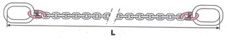
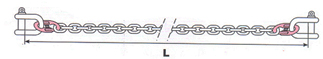
Type LTC-27 Large Link & Link Type
Type LTC-28 Large Link & Small Link Type
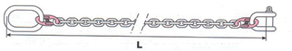
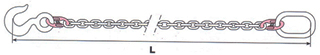
Type LTC-29 Large Link & Shackle Type
Type LTC-30 Shackle & Shackle Type
Type LTC-31 Hook & Large Link Type
How to order Lock & Set system assemblies
Determine the maximum load to be lifted by the chain sling you are ordering.
Choose the proper type of chain sling (single, double, etc.) which the size, shape and weight of the load dictate.
Estimate the approximate angle to the load in which the legs of the sling will be positioned for operation.
Select the proper attachments for your chain sling Hooks and Master Links for each type.
Determine the overall reach from bearing point on master link to bearing point on attachment.
Refer to the Working Load Limit Chart and to your pre-determined angle of the type sling you have selected.
Choose the chain size which meets your requirements.
When entering your order be sure you give complete information as to the size, reach and attachments required.
Note: Angle to the load on multiple leg sling will be 600 or greater as long as the distance between lifting eyes of load is NOT greater than reach shown on identification Tag
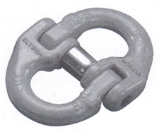
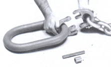
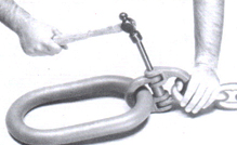
HOW TO ASSEMBLE CHAIN WITH QUICK COUPLING
(METHOD:1) Place the locking sleeve between the assembled half link forging
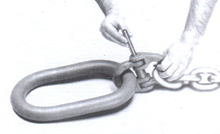
(METHOD:2) Drive the pin through the assembled links ends and sleeve until the end of the pin is flush with the outside of the connecting link halves.
(METHOD:3) Place the other side link on its outside and use the assembly link as system shown in method 1 & 2.