|
|
 |
|
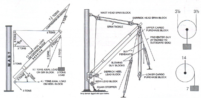
SIMPLEST FORM OF STRESS DIAGRAM FOR DETERMINING RESULTANT LOADS
|
|
|
 Oval Eye Oval Eye |
It has become increasing clear that some additional explanation of the system of testing and stamping of blocks is necessary.
(a) Double blocks are tested to twice the safe working load stamped on the block. The safe working load is the axial safe working load, i.e. the permissible load which the eye bolt may carry,
(b) Single blocks are also tested twice the axial safe working load, i.e. two times the permissible load which the eye bolt may carry. Single blocks are stamped with a safe working load of one half of the axial safe working load, i.e. the test load is four times the safe working load stamped on the block.
| Sheave Dia |
= at least - 12 times the diameter of the wire rope for which sheave is designed. |
| Rope Dia |
The safe working load for single fall wire rope is approximately one-fifth of the nominal breaking load of the rope. This is specified in IS: 2266/1989 for 6 X 37 construction. Fiber main core/independent Wire Rope Core with the minimum tenstile strength of 1770 N/mm2, the design of the blocks is based on the above standard calculations.
|
|
|
Block Twisting
|
Block twisting or cabling is one of the most frequently encountered wire rope problems in the construction industry. When this problem occurs, the wire rope is most often blamed, and other equally important factors in the operation are over looked. Personnel experienced with handling wire rope know that conventional wire ropes will twist or unlay slightly a load is applied. In a reeved hoisting system subjected to loading and unloading, such as a hoist line, this results in block twisting and possibly distortion of the wire rope. Cabling of the block most frequently occurs as the load in the wire rope is released and the falls are in a lowered position. Cabling may be considered as the twisting of the blocks beyond one-half revolution (180° twisting) of the traveling blocks. When this condition occurs, the operator shows good judgement in not making additional lifts until the conditions causing the problem are corrected. The following machine and site conditions should be investigated for possible improvement in block twisting.
1. Reduce wire rope length. Longer rope lengths cause more twisting than short rope length. This applies particularly to the amount of wire rope in the fall.
2. Reduce the amount of load lifted. Heavily loaded ropes have more torque and twist than lightly loaded ropes. This condition would also apply to the speed of loading or shock loading, since this condition also causes higher wire rope loading.
3) Eliminate odd-part reeving where the wire rope dead end is on the traveling block. Wore rope torque, from the application of load, is greatest at the rope dead end.
4. Relocate the rope dead end at the boom in order to increase the separation between the dead end and the other rope parts. This applies a stabilizing load directly to the traveling blocks. The original equipment manufacturer should be consulted before making this modification.
5. Increase sheave size. This increase the amount of separation between wire rope parts and may improve the situation by applying stabilizing loads and reducing the amount of rope torque transmitted to the traveling block.
6. Restrain the twisting block with a tag line. The use of rotation-reisitant wire ropes will not likely be required unless the intended length of rope fall exceeds 100 feet, on the length of the hoist line exceeds 100 feet. In the events these latter conditions exist, the end users should anticipate using a combination of the rotation-reisitant wire rope and the foregoing field suggestions.
|
|
|
|
|
|